
Tell me about: radio frequency filters
In the "Tell me about" section, we will try to expain in a few sentences the most important aspects to fully understand the ANR-LiLit project.
On this page, you will find an introduction to one of the essential components of data transmission devices: radio frequency filters.
What can I use it for ?
With the rapid development of worldwide mobile telecommunications, internet of things (IoT) and other means of wireless transmissions, there remains very few unused frequency bands. Furthermore, their access is regulated through licences that can be very expensive. In this overloaded traffic, devices have to be able to isolate the wanted information at the receiving hand, and to make sure not to disturb the other users at the transmitting hand. These are the two main functions of radiofrequency filters used in every connected equipment (mobile phones, watches, speakers, ...).
Simplified presentation of a radio transceiver (transmitter-receiver)
There are a lot of different architectures for radio frequency (RF) transceivers, however the working principle remains the same: the transmitter's role is to move the signal to transmit from low frequencies (the baseband) to radio frequencies, while the receiver does the exact opposite.
These operations involve modulating a characteristic (amplitude, phase, or frequency) of a precise reference RF signal called the carrier, using the signal that has to be transmited. Thus, the signal to be emitted is carried by this reference, and can then be retrieved by the receiver using that same reference.
RF transmitter
RF transmitters use an electronic mixer function to modulate the baseband signal (the one to transmit) by the carrier signal generated with a local oscillator (cf. block diagram to the left). The RF signal obtained has a frequency spectrum centered around the frequency of the oscillator (i.e. the carrier frequency). This signal is then amplified using a power amplifier and sent to the antenna after being filtered by the bandpass filter.
In fact, some of the actions described above, and particularly mixing and amplifying are carried out using active elements, more precisely: transistors. As a matter of fact, transistors have intrisic non-linear behaviour, and this characteristic is transmitted to mixers and amplifiers. These non-linearities can cause signal distorsion, but more importantly, can generate parasitical signals at frequencies different than the emission. There is a strict regulation regarding the levels of emitted signal so that one signal would not impact another. The bandpass RF filter therefore has the important task to ensure that the parasitical signal are not transmitted.
RF receiver
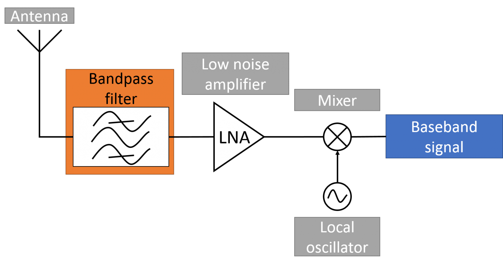 Simplified block diagram of a radio frequency (RF) receiver
At the other end of the transmission, there is a RF receiver, which duty is to extract the wanted signal from the received RF signal. This operation is again carried out using a mixer and a local oscillator working at the same frequency as the carrier signal used for the transmission.
The antenna acts as a passive element which detects all incoming electromagnetic waves within a certain frequency range. Hence, the antenna receives the transmitted RF signal, but also a myriad of parasitical signals originating from other communications. The issue regarding non-linearities is here a little different as they can generate intermodulation phenomenons, where a signal that would be at a different frequency than the reception could be modulated to the baseband along with the useful signal. And if the parasitical signal was not sufficiently attenuated, it could completely cover the wanted signal, and make it impossible to read. For that reason, it is absolutely critical to filter the signal directly after the antenna.
To sum up, at the emitting hand, RF filters have the essential task to prevent the transmission of any parasitical signal that could potentially interfere with other wireless communications, and at the receiving hand, its duty is to detect the wanted signal and shield it from parasites.
SAW and BAW: two different technologies for RF filtering
The size of the components used in mobile phones has been significantly decreasing with every new generation, and naturally, RF filters followed this trend.
The first RF filtering functions were conducted through dielectric filters using electromagnetic resonances. These components were very sturdy and cheap, but their bulk was a major drawback to their integration in mobile telecommunications. Therefore, acoustic components replaced their predecessors. They allow the propagation of elastic waves at a speed about 105 less important than electromagnetic waves, and as such, allowed to drastically reduce the size of the component for the same targeted frequency.
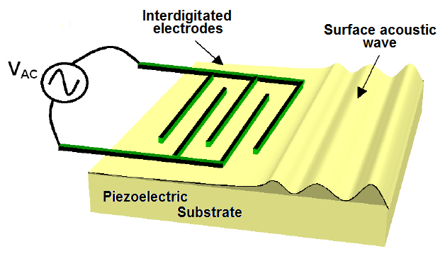 Schematic of the surface acoustic wave device of White and Voltemer (1965) [1]
Surface acoustic wave filters, or SAW
Surface acoustic wave filters (or SAW) were the first acoustic devices to be used for filtering applications, and their production has literally skyrocketed as a result of their integration in mobile phones.
The technology is based on the work of White and Voltmer who experimentally demonstrated in 1965 the generation of a surface acoustic wave on a piezoelectric substrate [1]. For that purpose, they patterned interdigitated electrodes on the surface of the substrate (schematic on the right). These interdigital transducers (IDTs) allow the generation of a surface acoustic wave on a piezoelectric layer through an alternating electrical signal. But this structure exhibits some limitations, particulatrly when the power density is high. And even if adjustements have been made by SAW designers over the years, these components remain incompatible with microelectronic fabrication technologies, forbidding their integration on silicon, and preventing the fabrication of a chip onto which all the functions of the telephone would be realised.
Bulk acoustic wave filters, or BAW
This incompatibility being very constraining, another technology made its debut in the early 80s that used bulk acoustic waves (or BAW). Indeed, the first device that uses bulk acoustic waves is none other than the quartz resonator, very well known today for its use in watches as time base. They are fabricated from thick single cristals that are thinned down to obtain the frequency required. In these components, the resonance frequency is inversely proportional to the thickness of the piezoelectric layer. Improvements in the field of piezoelectric thin film deposition hence permitted to reach high frequencies while keeping a high electromecanical coupling coefficient [2]. Zinc oxyde (ZnO) and aluminum nitride (AlN) are the most frequenctly used materials in these devices today.
Film Bulk Acoustic Resonator, or FBAR
 FBAR fabricated using bulk micromachining
 Thin deposited layers usually exhibit a polycristalline structure, but when they are properly oriented, they can be used to generate bulk acoustic waves just like the quartz resonator but with thin films this time.
To make the most out of BAW resonators, the resonating part has to be separated from the substrate. To do so, different methods were developped, the first being bulk micromachining, a technique that consists in etching the entirety of the substrate below the resonator [3-5]. The structure formed and showed here is called FBAR, short for Film Bulk Acoustic Resonator.
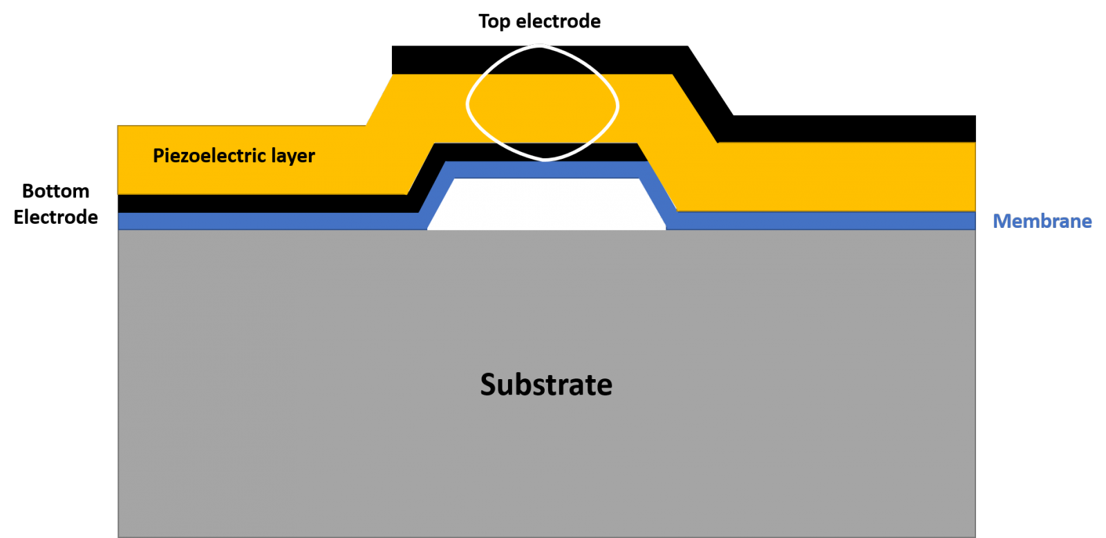 FBAR fabricated using surface micromachining
Unfortunately, this machining technique has the drawback of making the silicon substrate more fragile. To avoid this, a technique called surface micromachining [6] was developped. It takes advantage of a sacrificial layer to form an isolating cavity under the resonator thus keeping the structural integrity of the substrate (cf. schematic to the right) and opening new perspectives for the direct integration on circuit boards.
Solidly Mounted Resonator, or SMR
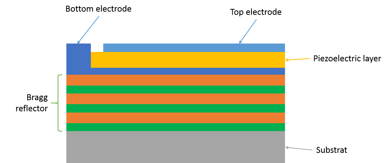 SMR with the Bragg reflector structure
Another isolating technique is based on the principle of the Bragg reflector which permits to reflect the acoustic energy generated by the resonator within a certain frequency range [7]. The Bragg reflector is composed of an alternation of thin layers that present low and high acoustic impedences, and the final structure is much more sturdy than the ones presented before as the whole stack is linked to the substrate (cf. shecmatic to the left). Hence, it was called SMR, short for Solidly Mounted Resonator.
All these achievements made it possible to go beyond the frequency limitation of the usual quartz resonator and allowed to reduce the size of the component even below that of SAW filters. But more importantly, it paved the way to integration of resonators and RF filters with high quality factor on circuit boards.
[1] R.M. White and F.W. Voltmer, "Direct Piezoelectric Coupling to Surface Elastic Waves". Applied Physics Letters, 1965. 7(12): 314-316.
[2] R.M. White, et al., "Bulk ultrasonic transducer employing piezoelectric film on thin metal sheet". IEEE Transactions on Sonics and Ultrasonics, 1981. 28(1): 8-13.
[3] K.M. Lakin and J.S. Wang, "UHF composite bulk wave resonators". in 1980 Ultrasonics Symposium. 1980. IEEE.
[4] T.W. Grudkowski, et al., "Fundamental mode VHF/UHF bulk acoustic wave resonators and filters on silicon. in 1980 Ultrasonics Symposium. 1980. IEEE.
[5] K. Nakamura, et al., "ZnO/SiO2-diaphragm composite resonator on a silicon wafer". Electronics Letters, 1981. 17(14):507-509
[6] H. Satoh, et al. "An air-gap type piezoelectric composite thin film resonator". in 39th Annual Symposium on Frequency Control. 1985. 1985. IEEE.
[7] L.N. Dworsky and L.C. Mang, "Thin film resonator having stacked acoustic reflecting impedance matching layers and method". 1994, Google Patents.
Anthony Almirall, 09/2019